

Resistance: working with resistors
Fundamentals of using resistors in Series and Parallel circuits
Series Circuits
Key Fundamentals
When Resistors are wired in Series, each individual resistance can be added up, to find the total circuit resistance
For example: in a circuit with 3x 100Ω resistors, the total circuit resistance will be 100Ω + 100Ω +100Ω = 300Ω
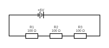
Example 1
In this example we connect 3 resistors (each 100Ω) in a straight line with a 6Volt battery pack. This type of configuration is called an “in Series circuit”.
We then use a multimeter to measure the total resistance of the circuit.
Tip: resistors are not polarized. That means it does not matter which end you face the resistor when connecting it to your circuit (unlike the LED we’ve encountered in projects 1 &2, which are polarity-sensitive)
Below is a schematic diagram you can follow to create this circuit:
Measuring resistance in a Series circuit
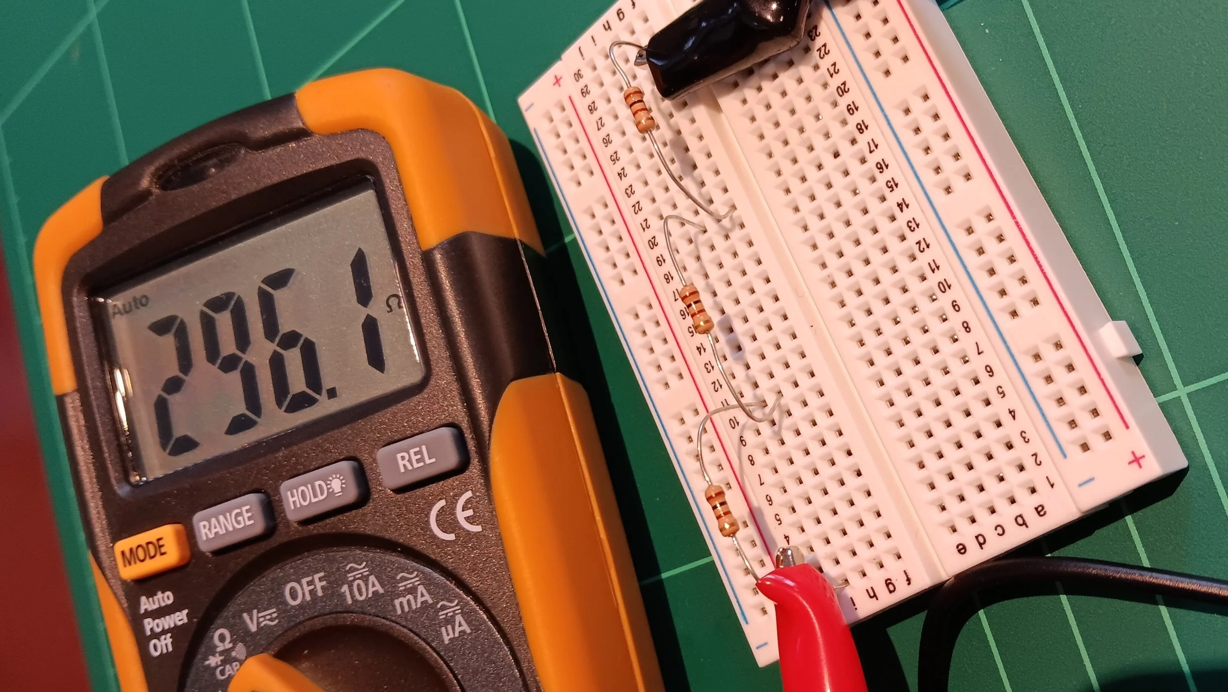
We can notice the total resistance across all 3 resistors is 300Ω (or very close, as detected by the multimeter in our example image above)
All multimeters and circuit components come with a certain margin of error in their measurement or values. This is called “tolerance”. Components and measuring tools with a lower tolerance are more precise, and usually also more expensive. This is a key factor that electrical engineers decide, when choosing components.
Parallel Circuits
Key Fundamentals
Resistors wired in parallel will lower the total circuit’s resistance
This is because we have created additional pathways for current to flow, therefore lowering the circuit’s total resistance